


Views: 0 Author: Site Editor Publish Time: 2026-08-20 Origin: Site


Investing in a pipe bending machine requires precise alignment between your specific manufacturing requirements and the equipment's core capabilities. Guessing on sizing limits invariably leads to scrapped material, premature machine failure, or wasted capital on overly-specced machinery. In heavy industrial and high-precision fabrication environments, assuming dimensional compatibility creates massive production bottlenecks and financial risks.
A machine’s true capacity is rarely dictated by a single metric alone. Instead, it relies on a strict mechanical calculation involving Outer Diameter (OD), Wall Thickness (WT), Center Line Radius (CLR), and the material's yield strength. Ignoring any of these critical engineering factors will easily compromise the structural integrity of your fabricated product.
This comprehensive guide breaks down the strict dimensional thresholds of industrial tube bending equipment to help you effectively evaluate, shortlist, and specify the right machine for your production floor. You will discover exactly how to balance complex material properties against various mechanical drive systems. We provide actionable steps to seamlessly match specific dimensional profiles against the most suitable forming technologies available today.
Capacity is multi-dimensional: Maximum pipe bending size depends heavily on the exact combination of OD, wall thickness, and material hardness, rather than just the raw diameter.
Drive types determine limits: Hydraulic tube benders excel at processing thick-walled, large-diameter pipes, while fully electric models dominate in thin-walled, high-precision aerospace or automotive applications.
Minimums matter as much as maximums: Running severely undersized pipes on high-capacity machines often causes clamping issues, material crushing, and wrinkling without highly specialized tooling.
Future-proofing requires a 20% buffer: Always specify a bending machine that can handle at least 20% more capacity than your current maximum requirement to ensure motor longevity and allow for future scalable production.
Operators and procurement managers frequently overestimate a machine's abilities by looking at a single number on a marketing specification sheet. To determine true technical feasibility, you must evaluate three core dimensional pillars simultaneously. Overlooking any of these variables guarantees poor bending results and equipment strain.
Many fabricators confuse Outer Diameter (OD) with Nominal Pipe Size (NPS), creating immediate tooling failures on the shop floor. Tube OD represents the exact, measurable outside physical dimension of the material. Conversely, Pipe NPS measures the standardized inside flow capacity used primarily in fluid transport. For example, a standard 2-inch NPS pipe actually has a measurable outside diameter of 2.375 inches.
Machine tooling operates strictly on exact OD measurements. Clamp dies, pressure dies, and bend dies require precise physical contact to function without friction loss. If you order tooling sets based on a 2-inch NPS measurement but process a 2-inch OD tube, the material will slip during the bend cycle. Always verify actual micrometer measurements against your tooling specifications before beginning production.
Wall thickness directly dictates the required bending moment and alters the physical behavior of the metal during plastic deformation.
Thin walls (Schedule 5/10): These dimensions carry a notoriously high risk of wrinkling on the inside radius and severe ovality on the outside radius. They demand highly precise machine control. You must utilize internal mandrels and properly raked wiper dies to support the structural integrity of the tube throughout the bend.
Thick walls (Schedule 40/80+): Thick material resists deformation aggressively, requiring immense mechanical torque. This physical resistance ultimately dictates the maximum safe limit of the machine's drive system. While thick walls rarely wrinkle, they place massive strain on clamping mechanisms and hydraulic cylinders.
You simply cannot evaluate pipe size limits without addressing material hardness. Bending a 2-inch copper pipe requires a vastly different mechanical force profile than bending a 2-inch stainless steel pipe. Yield strength determines the exact point where metal permanently deforms rather than springing back to its original shape.
Mechanical engineers calculate the section modulus to understand this physical resistance. High-yield materials multiply the required machine tonnage exponentially. A machine comfortably bending large aluminum tubes may stall completely when fed a significantly smaller carbon steel tube. Always cross-reference your specific material grade against the manufacturer's base capability charts before finalizing a purchase.
Standard Material Yield Comparison Chart
Material Type | Typical OD Range (Inches) | Relative Yield Strength | Common Application |
|---|---|---|---|
Copper (Annealed) | 0.25 - 4.0 | Low | HVAC, Plumbing |
Aluminum (6061-T6) | 0.50 - 5.0 | Low to Medium | Automotive, Aerospace |
Carbon Steel (Mild) | 1.0 - 10.0+ | Medium | Structural, Industrial |
Stainless Steel (304/316) | 0.50 - 8.0 | High | Sanitary, Chemical |
Titanium Grades | 0.25 - 3.0 | Very High | Aerospace, Medical |
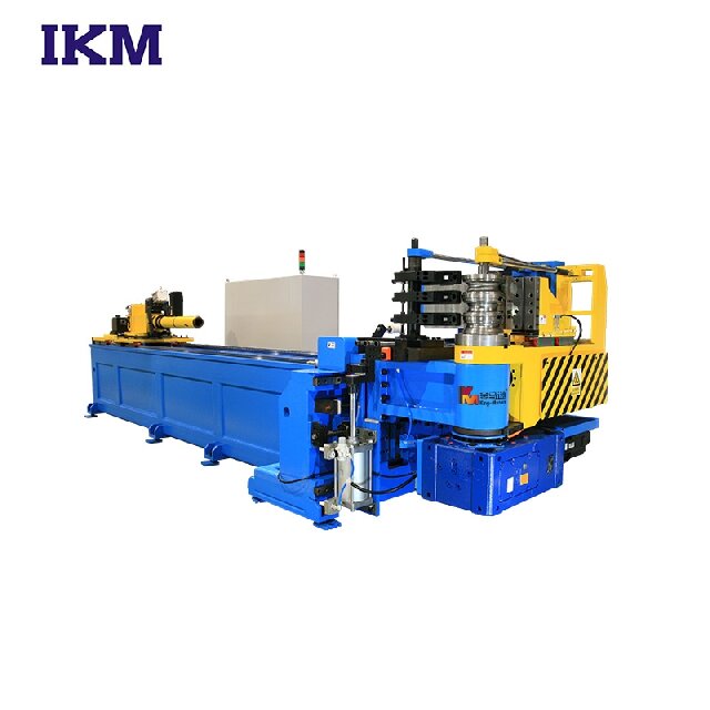
Machine sizing relies heavily on the underlying power mechanism driving the bending head. Different drive systems handle specific dimensional ranges and production requirements better than others. Understanding these structural thresholds prevents catastrophic equipment failure and ensures maximum ROI.
Heavy industries and structural fabricators rely heavily on the hydraulic tube bender for massive dimensional requirements. These robust machines utilize pressurized fluid dynamics to generate extreme mechanical force. They are best suited for structural steel, boiler tubes, and heavy schedule pipes. You will commonly see them successfully processing materials ranging from 3 inches to well over 10 inches in OD.
When applying a procurement decision lens, evaluate raw torque output. Hydraulic systems deliver maximum pushing power for thick-walled applications. However, they do sacrifice some micro-precision. Fluid dynamics naturally experience slight lag and viscosity changes due to temperature variations during prolonged operation. This makes them ideal for shipyards, energy sectors, and heavy infrastructure projects where brute force takes priority over rapid, complex multi-radius operations.
Modern precision manufacturing environments heavily favor the full electric pipe bending machine. Driven entirely by highly calibrated, multi-axis servomotors, these units excel in unmatched accuracy and speed. They are the standard for aerospace tubing, intricate automotive exhaust systems, and sanitary stainless steel lines. Their optimal processing range typically falls between 0.25 inches and 6 inches OD.
Through a strategic decision lens, electric models offer superior repeatability and zero thermal drift. They minimize wall thinning on delicate, thin-walled tubes. Servomotors provide instant torque feedback, allowing the advanced machine controller to adjust pressure in real-time. Furthermore, electric benders feature a vastly lower maintenance footprint because they eliminate hydraulic fluid leaks, valve replacements, and filter changes. However, they generally cap out at lower maximum diameters compared to their heavy-duty hydraulic equivalents.
Certain dimensional limits stem directly from part geometry and factory space rather than raw machine power. The bidirectional CNC pipe bender is engineered to solve complex clearance issues. These highly specialized machines are best for complex furniture frames, intricate HVAC copper routing, and dense automotive fluid lines.
Applying the decision lens reveals unique machine sizing constraints. These benders are capable of right-hand and left-hand bending in a single continuous operational cycle. Because of this, sizing is often limited by the machine's physical clearance (known as interference zones) rather than just servo motor torque. You must evaluate them based on their ability to handle multi-radius bends on small-to-medium OD pipes without colliding into the machine carriage or floor. If your part features tight consecutive bends in opposing directions, bidirectional clearance matters significantly more than maximum OD torque capacity.
Equipment buyers naturally focus their attention on the maximum listed capacity. However, pushing a machine to its absolute limits daily creates severe operational headaches. Similarly, running tiny micro-tubes on massive, heavy-duty machines introduces unexpected defects and high scrap rates.
Operating a bending machine consistently at 100% of its rated OD and WT limits accelerates mechanical wear rapidly. Servomotors will overheat, hydraulic pumps will blow seals, and expensive tooling components will fatigue prematurely.
A machine rated for 4-inch pipe can certainly bend a 4-inch pipe. However, doing so for three shifts a day severely shortens the equipment's overall lifespan and maintenance intervals. Best practices dictate keeping daily production volumes well within the middle 80% of the machine's rated capacity chart. Reserve the absolute maximum capacity for occasional, specialized prototype runs.
Conversely, drastic downsizing presents unique engineering challenges. Running a 0.5-inch tube on a machine designed for 6-inch pipe often results in poor clamping force distribution. The massive clamping cylinders cannot apply the gentle, nuanced pressure required for small diameters, easily crushing delicate thin-walled tubes.
Large machines also suffer from excessive carriage vibration when processing micro-tubing. Furthermore, you will face significant difficulty sourcing compatible micro-tooling. Tooling manufacturers rarely design half-inch die sets to fit the massive mounting posts of a heavy-duty bender. The physical dimensional mismatch causes alignment issues and increases production scrap rates.
A machine's stated capacity always assumes the use of perfectly matched, optimal tooling. The bare bending machine itself holds no magical capabilities without its dies. Missing, worn, or incorrect tooling artificially reduces the machine's viable size range.
If you attempt to bend a thin-walled 3-inch tube without a proper mandrel, the tube will collapse inward. The machine possesses the driving power, but it lacks the internal structural support. Wiper dies prevent inside radius wrinkling, while pressure dies control material drag. You must calculate tooling requirements into your maximum size expectations. A high-capacity machine remains functionally useless if you fail to equip it properly for the job.
Bending machine manufacturers typically quote maximum capacities based on standard mild carbon steel. Changing your base material completely alters the acceptable OD and WT parameters. You must actively adjust your sizing expectations based on the specific metallurgy of your project.
Soft metals offer relatively low yield strength. Bending machines can generally handle larger diameters of soft metals relative to their baseline steel rating. For instance, a machine maxed out at 2-inch steel might successfully process 2.5-inch copper or aluminum without stalling.
However, these materials are highly prone to stretching and thinning. They can tear easily along the outside radius during a tight bend. While the machine possesses enough torque, it requires highly calibrated CNC controls to prevent severe wall thinning. You must use precise carriage boost pressure to actively push material into the bend zone, reducing stretch.
This category represents the baseline standard for most manufacturer capability charts across the industry. Carbon steel offers predictable springback, standard scaling, and reliable formability.
When sizing a machine specifically for mild steel, you can generally trust the published specification sheets. The material behaves consistently under mechanical pressure, and standard tooling formulas apply directly. It strikes an excellent operational balance between structural rigidity and forming ease.
Exotic alloys and hard metals require an immediate capacity de-rating. You must never assume a machine's mild steel capacity applies safely to stainless steel or aerospace alloys.
These metals feature extreme yield strength and exhibit severe springback behavior. Furthermore, they work-harden rapidly during the cold bending process. A machine rated for 3-inch mild steel may only safely and consistently bend 2-inch stainless steel. Titanium and Inconel require even further capacity reductions. Pushing hard metals to the machine's absolute maximum mild-steel limit guarantees motor stalls or broken clamp chains. Always consult the machine manufacturer's specific hard-metal degradation charts.
Procuring the right CNC or hydraulic machine demands methodical evaluation. You must strictly align your factory floor realities against theoretical machine capabilities. Follow these structured engineering steps to secure the optimal equipment.
Do not guess your dimensional needs or rely on outdated assumptions. Conduct a rigorous, data-driven audit of your current and future engineering drawings.
Document the absolute largest OD you currently process on the floor.
Identify the thickest wall dimension across all active part numbers.
Record the toughest material grade and alloy in your regular inventory.
Locate the tightest Center Line Radius (CLR) required by your most complex designs.
This organized data forms your baseline specification matrix. It provides vendors with exact, actionable parameters for accurate capability matching.
Analyze your production volume distribution carefully. If 80% of your daily work involves 2-inch tubing and only 20% requires 4-inch tubing, rethink your purchasing strategy.
Evaluate the operational return of dedicating a faster, highly precise 2-inch capable machine to your main, high-volume production line. Huge bending machines move slower, consume vast amounts of electrical power, and require massive floor space. Outsourcing the occasional 4-inch massive pipes often proves far more financially efficient than bogging down your daily throughput with an oversized, sluggish machine. Optimize your capital investment for your highest volume constraints.
Changing pipe sizes requires changing bending tools. Ensure the shortlisted manufacturer provides seamless, efficient tooling changeover systems for your full range of required sizes.
If swapping from a 1-inch setup to a 3-inch setup takes your operators four hours, your production bottlenecks immediately, destroying ROI. Look for modern quick-release clamping mechanisms and drop-in die mounts. Verify tooling stackability for complex multi-radius jobs. Efficient size changes matter just as much to your bottom line as maximum capacity limits.
Never purchase industrial equipment purely off a marketing brochure. Always request a "test bend" or detailed capability audit from the manufacturer. Send them your specific material grade, precise dimensions, and exact CLR requirements. Seeing your absolute toughest part successfully formed before final procurement provides the ultimate validation of the machine's true capacity limit.
A pipe bending machine's capacity is never a single, static number. It represents a strict engineering intersection of outer diameter, wall thickness, material grade, and the machine's drive type. By comprehensively understanding how these variables interact dynamically, you prevent catastrophic equipment failures, eliminate material waste, and ensure high-quality fabrication yields.
Base your final procurement decisions strictly on operational evidence, thorough material audits, and specific engineering charts. Ignore generalized marketing claims that fail to account for material hardness and yield strength. Always build a minimum 20% capacity buffer into your final selection to protect your equipment from premature mechanical wear and allow for business growth.
Contact our expert engineering team today for a comprehensive technical sizing assessment. We will analyze your exact pipe dimensions, radii requirements, and material grades to seamlessly match you with the perfect bending technology for your production floor.
A: Yes, provided the machine has adequate tonnage capacity and you install the correct profile-specific tooling. However, the maximum diagonal dimension of square or rectangular tubing will inherently reduce the machine's overall rated capacity compared to standard round pipe. Square tubing resists deformation differently at the corners and requires highly specialized wiper dies and mandrels to prevent inward wall collapsing.
A: Attempting to exceed the rated capacity can cause severe structural damage to the bending carriage, blow high-pressure hydraulic seals, burn out electrical servomotors, and result in immediate, expensive tooling failure. Most importantly, it creates major safety hazards for operators due to the risk of flying metal or snapping heavy-duty clamp chains.
A: No. Manual benders and standard electrical contractor conduit benders are typically limited to small diameters (usually up to 2 inches) and very thin walls. Automated CNC and heavy motorized machines are strictly required for heavy schedule industrial pipes, complex multi-radii geometries, and high-volume manufacturing repeatability.
A: Yes, absolutely. A tighter CLR requires significantly more mechanical force and drastically increases the risk of outer wall thinning and inner wrinkling. Pushing a machine to its maximum OD on a very tight CLR usually requires advanced internal mandrels and specialized carriage booster systems to prevent catastrophic material failure.


