


Views: 0 Author: Site Editor Publish Time: 2026-08-13 Origin: Site


In modern metal fabrication, bend angle accuracy acts as a direct driver of production profitability. Even minor deviations in a single bend compound rapidly, causing elevated scrap rates and costly downstream assembly failures. Manufacturers cannot afford guesswork when bending complex geometries.
The industry has shifted focus from raw brute force toward highly intelligent control systems. Today, pinpoint accuracy relies on a sophisticated interplay between mechanical drive components, real-time digital feedback loops, and material physics. Modern machinery treats the bending process as a dynamic calculation rather than a static physical motion.
Production managers and procurement engineers need a clear framework to evaluate these capabilities. We will explore exactly how different bending technologies calculate, achieve, and maintain strict angle precision on the factory floor. You will learn how to match standard requirements against specific machine capabilities.
Bend angle (C-axis) control relies on closed-loop feedback systems, primarily using absolute or incremental rotary encoders.
The choice of drive system directly impacts repeatability; servo-driven systems offer higher precision than traditional hydraulic valves.
Advanced control interfaces actively calculate and compensate for material springback, reducing manual trial-and-error.
Evaluating a machine requires balancing required tolerances against cycle times, operator skill levels, and machine capabilities.
To prevent over-travel during operation, a commercial Pipe Bending Machine relies heavily on closed-loop feedback systems. Moving heavy steel tubing generates significant physical inertia. Without a system to constantly monitor arm position, momentum would push the bend past its programmed target. Closed-loop controls solve this. The machine controller sends a movement command. Sensors read the actual physical movement. They report this data back instantly. This constant loop ensures the bending arm stops exactly at the required angle.
Rotary encoders serve as the primary sensors in this process. Manufacturers mount them directly on the bend arm or tooling axis to measure real-time position. You will encounter two main types: absolute and incremental encoders.
Absolute encoders assign a unique digital code to every possible position of the bend arm. They remember their exact location even after a total power loss. Incremental encoders work differently. They count electronic pulses from a zero point. If a power outage occurs, incremental systems require an operator to perform a manual homing cycle to find zero again. For high-volume production, absolute encoders provide superior reliability and faster startup times.
Historically, machinery relied on mechanical limit switches. An operator would manually set physical stops to halt the bend arm. Modern equipment replaces these legacy physical stops with programmable logic controllers (PLCs). Digital control eliminates mechanical wear entirely. It also slashes setup time. Operators simply type the desired angle into a touchscreen instead of wrenching physical metal blocks into place.
When discussing resolution and tolerance, commercial expectations have tightened significantly. A quality rotary encoder reads position down to tenths or even hundredths of a degree. High encoder resolution translates directly into highly accurate finished parts. However, mechanical slop in gears can still compromise a high-resolution sensor. The entire mechanical chain must match the digital precision.
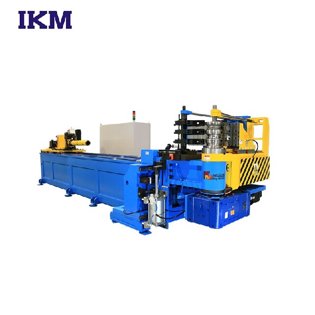
The power source moving the bend arm fundamentally dictates the machine's repeatability over a long production shift. The choice between hydraulic and electric systems changes how the machine applies and stops force.
A standard hydraulic tube bender achieves angle control via proportional valves. These valves regulate the exact flow of pressurized hydraulic fluid into the bending cylinders. By opening or closing the valves in tiny increments, the controller manages the speed and stopping point of the bend arm.
Implementation reality presents a few challenges. Hydraulic systems remain highly susceptible to fluid temperature variations. As a machine runs through a long shift, hydraulic fluid heats up. Heat changes fluid viscosity. Changed viscosity alters pressure drops across the valves. This thermal drift causes tiny angle deviations. Operators must periodically recalibrate the machine during tight-tolerance runs. Despite these quirks, hydraulic power excels in high-wall-thickness, heavy-duty applications. When bending massive structural steel, raw force often outweighs micro-precision.
In contrast, angle control in a full electric pipe bending machine is driven entirely by AC servo motors paired with rigid planetary gearboxes. There is no fluid. There are no valves.
This implementation reality delivers instantaneous torque. Servo motors provide incredible stopping power. Because they do not rely on fluid, they eliminate thermal drift entirely. The machine will hit the exact same angle on the first bend of the morning as it does on the last bend of the night. This stability results in highly repeatable, aerospace-grade tolerances. Consequently, manufacturers experience significantly lower scrap rates when running expensive materials like titanium or thin-walled stainless steel.
We cannot view the bend angle (the C-axis) in isolation. In real-world fabrication, the final part shape relies on how the C-axis interacts with other movements. The machine must also control the distance between bends (the Y-axis) and the plane of rotation (the B-axis).
Complex tubular parts, such as automotive exhaust headers or furniture frames, require continuous movement across all three axes. A highly capable bidirectional CNC pipe bender excels here. This machine offers both left-and-right bending capabilities. Traditional machines bend in only one direction, which often causes complex parts to crash into the machine bed. Bidirectional systems require sophisticated software to dynamically mirror bend angle calculations. The controller maps the part in 3D space. It actively plans a route to avoid collision paths during operation.
This brings us to interpolation. Interpolation defines how the CNC controller synchronizes the feeding, rotating, and bending axes simultaneously. Instead of moving one axis at a time, the machine pushes, twists, and bends in one fluid motion. This smooth synchronization maintains material integrity. It prevents thinning on the outside of the tube. It also keeps cycle times incredibly short while maintaining strict control over the final angle.
Even with perfect encoders and servo motors, physical material properties complicate angle control. You must address the springback problem.
When you program a machine to bend a tube to 90 degrees, the metal will not rest at 90 degrees once released. Material yield strength causes the tube to spring open slightly. The programmed machine angle is rarely the final resting angle. To achieve a true 90-degree bend, the machine might need to pull the arm to 93 degrees.
Modern CNC controllers handle this through software-driven compensation. They utilize pre-loaded material libraries to automatically calculate these overbend requirements. An operator simply inputs the material type, wall thickness, and outer diameter. The software predicts the behavior.
Industrial software typically uses two different formulas to manage this phenomenon:
Calculation Method | How It Works | Best Use Case |
|---|---|---|
Proportional Springback | Calculates a percentage of the total bend angle (e.g., adds 5% extra to any programmed angle). | Varying angles across a single part. Provides accurate scaling for deep bends. |
Constant Springback | Adds a fixed degree amount regardless of the bend size (e.g., always adds 2 degrees). | Predictable, single-angle production runs where material batch consistency is high. |
Beyond theoretical software compensation, high-end machines feature in-process inspection integrations. These systems use laser measurement or tactile probing tools. They verify the angle mid-cycle before releasing the tube. If the material springs back more than expected and misses the tolerance, the system recognizes the error immediately. It instructs the machine to re-strike the tube, adding the exact fraction of a degree needed to perfect the part. This closed-loop material verification drastically reduces scrapped parts.
Selecting the right bending technology requires a structured evaluation framework. You must align your production needs with machine capabilities to ensure a strong return on capital expenditure.
First, evaluate tolerance requirements against capital expenditure. You want to avoid over-specifying equipment. Standard structural requirements for handrails or basic frames pair perfectly with NC (Numerical Control) or hydraulic setups. They offer excellent value for standard work. Conversely, you should reserve full-electric CNC machines for aerospace, medical, or automotive specifications. These sectors demand the micro-precision that only servo-driven systems provide.
Next, carefully assess operator dependency and the hidden costs of training. Older manual or basic hydraulic machinery requires highly skilled operators who understand complex angle math and material behavior. Finding these operators proves difficult today.
Modern CNC systems lower the skill floor required for daily operation. They shift complex angle math directly to the software. You can train a new operator on a touchscreen CNC interface much faster than on manual valve adjustments.
Finally, evaluate controllers based on integration and data tracking capabilities. Industry 4.0 compliance requires machines to talk to your network.
Look for the following integration capabilities:
Direct CAD/CAM Imports: The controller should accept STEP or IGES files directly, eliminating manual data entry errors.
XYZ to YBC Conversion: The software must seamlessly convert 3D coordinates into machine-readable bend data.
Production Data Logging: The machine should output cycle times, scrap rates, and fault codes to your central ERP system.
Remote Diagnostics: Factory technicians should be able to log into the machine remotely to troubleshoot encoder faults or software glitches.
Machines offering these digital features will optimize production workflows and drastically reduce time spent programming new parts.
Bend angle control represents a complex synthesis of mechanical drive technology, encoder accuracy, and intelligent software compensation. Replacing manual guesswork with closed-loop feedback systems guarantees repeatable precision. Electric servo drives eliminate thermal drift, while modern PLCs and rotary encoders ensure the bending arm stops exactly on target every single cycle.
When shortlisting equipment, we advise buyers to demand real-world test bends on their specific production materials. Do not rely solely on brochure specifications. Physical test bends will validate a machine’s springback compensation software and prove its repeatability before purchase.
We highly encourage you to consult directly with applications engineers. Ask them to run a cycle-time and tolerance analysis on your specific part blueprints. This empirical data will definitively reveal which control system aligns best with your production goals.
A: NC (Numerical Control) systems typically program a single axis, requiring operators to manually advance or rotate the tube between bends. CNC (Computer Numerical Control) handles multi-axis automated synchronization. A CNC system controls the feeding (Y), rotating (B), and bending (C) axes simultaneously, creating complex geometries without manual intervention.
A: Theoretically, yes, for a short period. However, hydraulic machines struggle with long-term repeatability under thermal load. As fluid heats up during a shift, viscosity changes cause minor pressure fluctuations, leading to angle drift. Fully electric machines use servos, eliminating fluid and thermal drift entirely.
A: Modern machines rely on predictive software algorithms. Operators input material type, diameter, and wall thickness. The software references pre-loaded material libraries to estimate yield strength. Operators also perform trial bends, entering the actual springback data into the interface, which the machine then uses to calibrate all future bends.
A: Yes, many companies retrofit older hydraulic frames with modern PLCs, touchscreen interfaces, and higher-resolution encoders. This improves digital control and setup times. However, retrofitting cannot fix inherent mechanical wear in legacy gearboxes or cylinders. You must weigh retrofit costs against buying a new, fully warranted machine.


